
Plan Elements
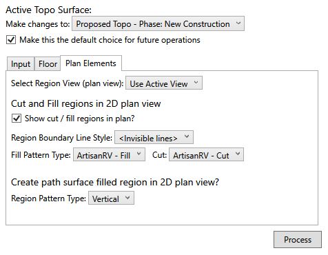
Plan Elements enable the Cut and Fill regions to be displayed with identifiable hatch pattern and colour to aid construction of the modified topography on site. Cut and Fill Regions are defined by selecting from the Plan Elements area before picking Process on the Create Linear Path dialog.

From the Plan Elements area, users are able to select the Plan View to display the Cut and Fill regions as well as the hatch pattern type for the Cut and Fill areas.
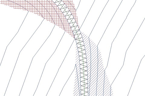
When processed, the defined Plan Elements are displayed in the selected Plan View.

The example above shows the area of Cut as a cross-hatch (in red) and the are of Fill as a diagonal hatch (in blue ).
From the Plan Elements area, users are able to define a Hatch Pattern for the Linear Path in a 2D Plan view .